EFHW Transformer Calculator
Estimate impedance ratio and transformer turns ratio for an end-fed half-wave transformer.
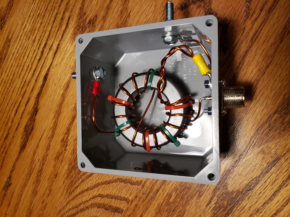
Why the transformer is part of the antenna
The photograph shows the practical component this calculator is concerned with: an end-fed half-wave transformer built around a toroidal core inside a weather-resistant enclosure. An EFHW radiator presents a much higher impedance at its end than a typical 50-ohm transceiver expects, so the transformer provides the impedance transformation between the antenna and the coaxial feedline. The physical winding, core material, wire size, capacitance and enclosure all matter when the transformer is taken from a spreadsheet to a real station.
The calculator estimates the required impedance ratio and the corresponding turns ratio. The key relationship is that impedance transforms as the square of the turns ratio. For example, a nominal 2,500-ohm antenna load requires a turns ratio near the square root of 2,500/50, or about 7.1:1. The exact practical design is not determined by this number alone. An EFHW can have a complex impedance that changes with frequency and installation, and the transformer's leakage inductance, stray capacitance and core losses can affect the result.
Treat the calculated turns ratio as a starting point for winding selection. Use the intended core material and verify that the core can tolerate the expected RF voltage and power. Keep the winding layout consistent with the chosen design and provide adequate insulation around high-voltage points. After assembly, test the transformer at low power with a suitable resistive load before connecting the antenna. Then evaluate the complete antenna system, because the transformer, radiator, counterpoise or coax shield and surroundings form one RF system. A measured load test before field deployment is worth doing whenever the transformer will see meaningful transmit power.
Turns ratio follows Nhigh/Nlow = √(Zhigh/Zlow). This is a starting transformer design; actual EFHW transformers depend on core material, winding arrangement, frequency range, power, leakage inductance and losses.
Choose the transformer ratio carefully
An EFHW transformer works by impedance transformation rather than by making the antenna intrinsically 50 ohms. Turns ratio, core material, winding layout and common-mode current all affect the finished system.
Choose a core appropriate for the operating power and frequency range, and keep the high-voltage end of an end-fed antenna physically clear. A tuner can hide a poor installation, so measure the antenna system rather than relying only on the tuner display.
The calculated turns ratio is a design starting point. Check the transformer with a known load or an antenna analyser where possible, especially before applying full transmitter power.
Next step in the workflow
Use the calculation as a starting point, then move to the tool that answers the next practical question.