End-Fed Half-Wave (EFHW)
Half-wave wire fed at the end through a high-ratio unun (usually 49:1). Excellent multi-band portable antenna.
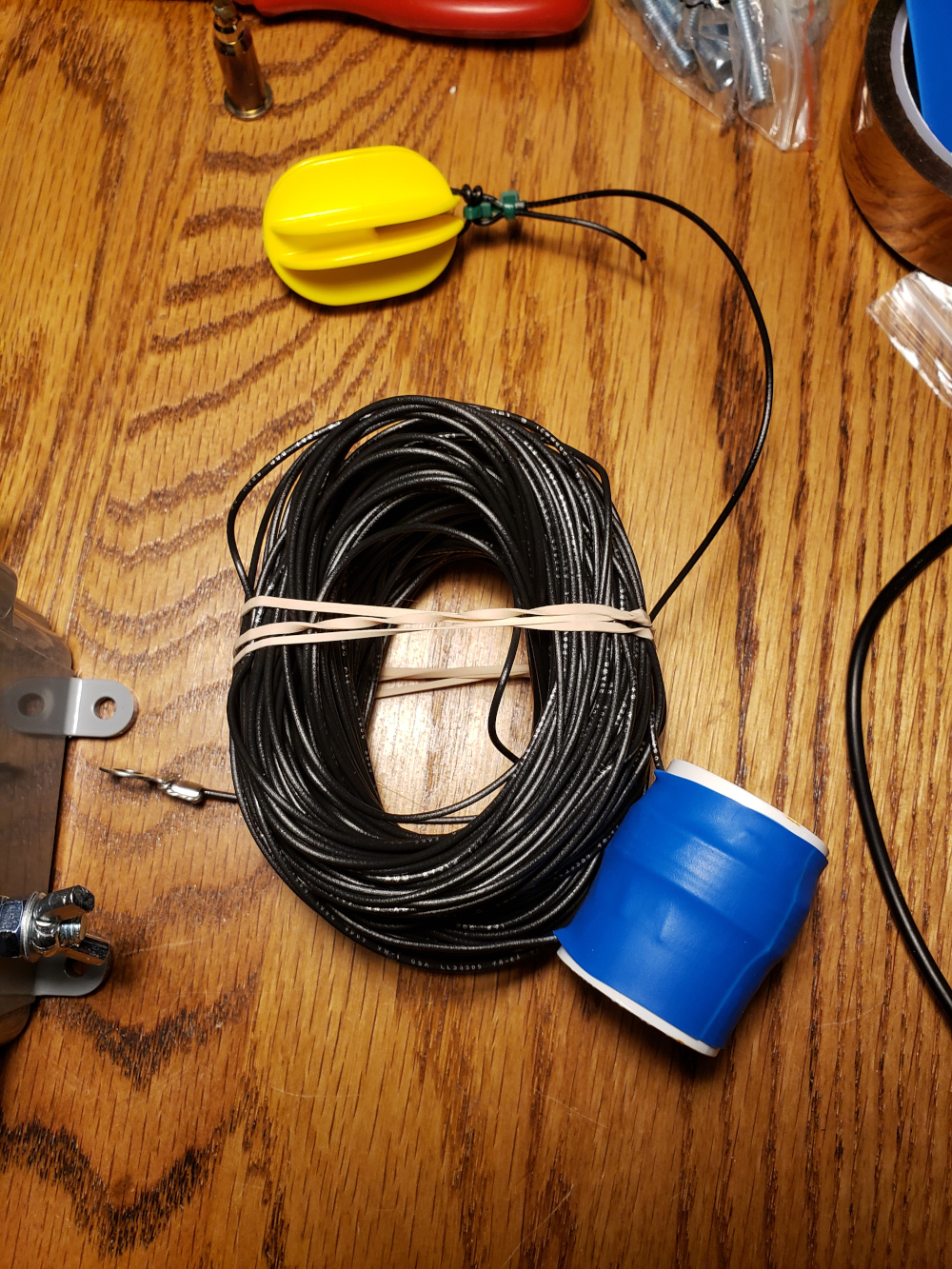
How the end-fed arrangement behaves
The photograph shows a practical end-fed half-wave arrangement: a long wire radiator terminates at an end-fed transformer or matching enclosure, with an insulator and supporting cord used to deploy the wire. This configuration is popular for portable operation because the feedpoint can be placed near the operating position while the radiator runs upward, horizontally or as a sloping wire. The apparent simplicity hides an important electrical detail: the impedance at the end of a half-wave radiator is high and varies with the exact geometry and environment.
The calculator provides a starting wire length from the operating frequency. In practice, do not assume that a nominal half-wave formula will be the final dimension. End effects, wire insulation, conductor diameter, installation height and nearby structures all shift resonance. Multiband EFHW installations add another layer of complexity because the transformer and any loading coil or compensation section must work across several frequency regions.
The return-current path also deserves attention. An EFHW can operate with little or no deliberately attached counterpoise in some installations, but the RF return still has to complete the circuit through some combination of the transformer, feedline shield, radio chassis, counterpoise and surrounding capacitance. Unwanted common-mode current can change tuning and cause RF in the shack. A suitable choke and deliberate feedline routing can help. Build the radiator slightly long, install it in its intended position, measure the resonant points, and trim conservatively. The image is a useful reminder that the real antenna is a complete installed system, not just a calculated length of wire.
Length
EFHW Notes
High feed-point impedance (~2000–3000 Ω) is transformed to ~50 Ω. Works well on odd harmonics of the fundamental.
Typical harmonic coverage
- 40 m fundamental → 20, 15, 10 m usable
- 80 m fundamental → 40, 20, 15, 10 m (with some compromise)
Assumptions & limitations
- Length is a free-space half-wave approximation with end-effect. Height, counterpoise and the transformer all shift the actual resonance.
- No modelling of common-mode current on the feedline or of the counterpoise system.
Practical gotchas
- An EFHW without any counterpoise or with a poor one often forces the coax shield to become part of the antenna — RFI in the shack is the usual symptom.
- The 49:1 (or 64:1) transformer must handle the voltage; cheap cores can heat or saturate at higher power.
- Harmonic coverage is convenient but the SWR and efficiency are rarely equal on every band.
Next step in the workflow
Use the calculation as a starting point, then move to the tool that answers the next practical question.