Fan Dipole Calculator
Calculate multiple half-wave dipole elements for a fan dipole and show each total and per-leg length.
How the parallel elements interact
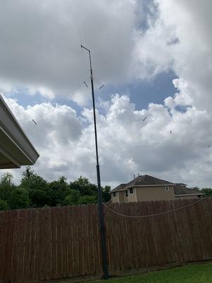
The photograph shows why a fan dipole is useful when one support point and one feedline need to serve several HF bands. Multiple dipole elements share a common feedpoint and spread away from the centre, with each pair cut for a different band. In a real installation the wires may be arranged horizontally, as an inverted-V, or in another geometry dictated by available supports. The photograph also illustrates an important practical fact: the final shape is determined as much by the property and supports as by the calculator.
Each element is approximately a half-wave dipole for its target band. The calculator therefore estimates a separate half-length for each selected frequency. The wires interact with one another, so the result is not simply the same as installing each dipole alone. Element spacing, angle, height, conductor diameter and the order in which the wires are physically arranged can shift resonance. When adding a new element, expect to re-check the existing bands rather than assuming they will remain unchanged.
Build each pair slightly long and label the wires before raising the antenna. Tune the lowest-frequency or longest element first, then work upward while checking the previously adjusted bands after every major change. Keep the feedpoint mechanically secure and use spreaders or spacers that maintain separation without introducing unwanted conductive coupling. A balanced feed arrangement and appropriate common-mode control can improve measurement repeatability. The image is intentionally matched to the page because it shows the actual multi-element, multi-support character of a fan dipole. Use the calculator to establish starting dimensions, then use an analyser in the final installation to determine the practical trim lengths.
Enter one frequency per band. The calculator returns the total half-wave element length and the length of each side.
Manage element interaction
A fan dipole places several resonant elements on the same centre support. The elements interact, so the calculated lengths are starting dimensions rather than guaranteed final resonance points.
Keep the elements separated and arrange them so they do not collapse into a single bundle. Small changes in spacing and the angle of the wires can shift resonance, particularly on the lower bands.
Build each leg slightly long and trim one band at a time. Once the physical arrangement is fixed, re-check the higher bands because changes to the lower elements can affect the overall structure.